Mini Relay 4 Pin Micro Relay Wiring Diagram

Wiring Diagram 4 Pin Relay Fitfathers Me Fancy At Relay Wiring Diagram 4 Pin Relay Electrical Circuit Diagram Automotive Electrical

Micro Mini And Pcb Relays
12 Volt Car Relays Used In Automotive Industry
Diy Bussmann Rtmr Fuse Block Part 4 Wiring And Schematics Bodenzord
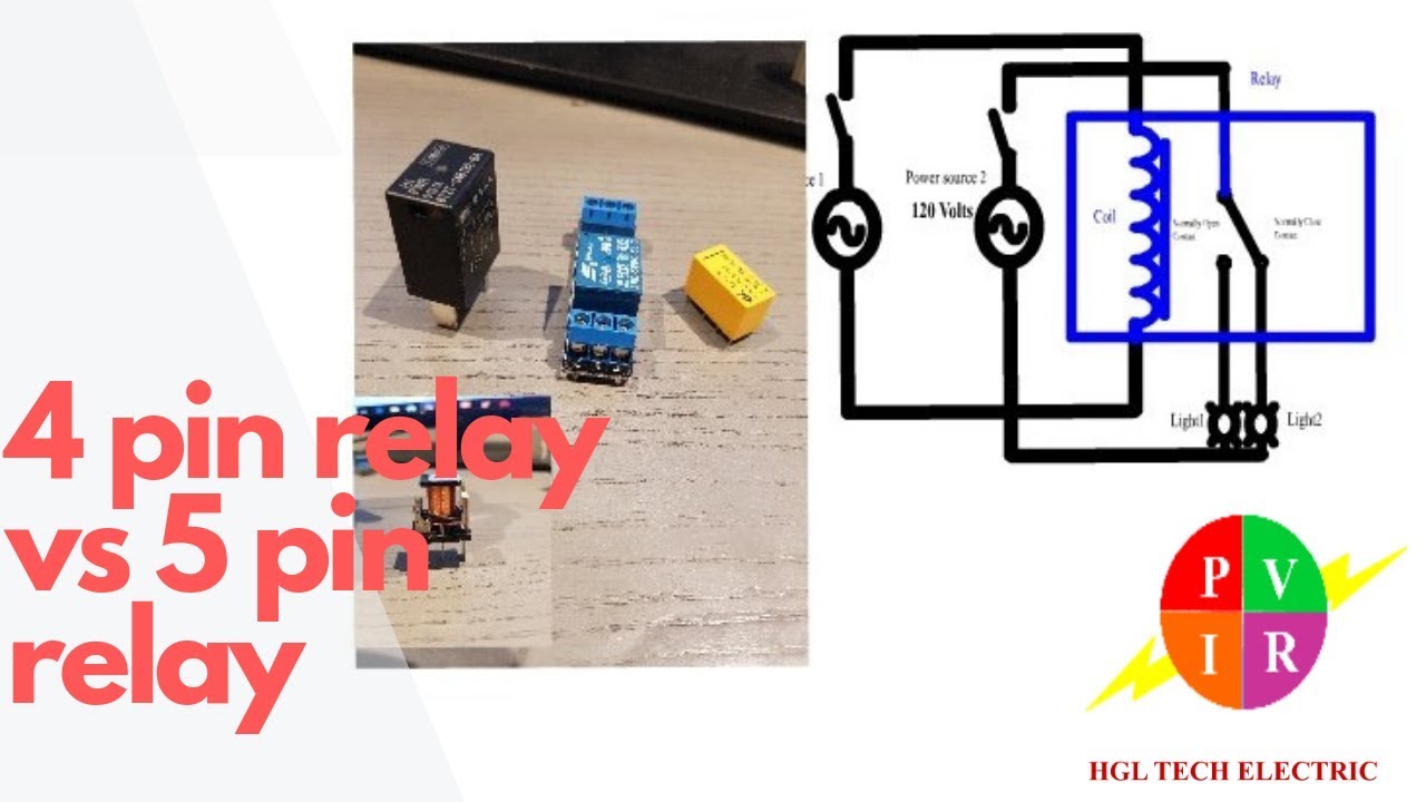
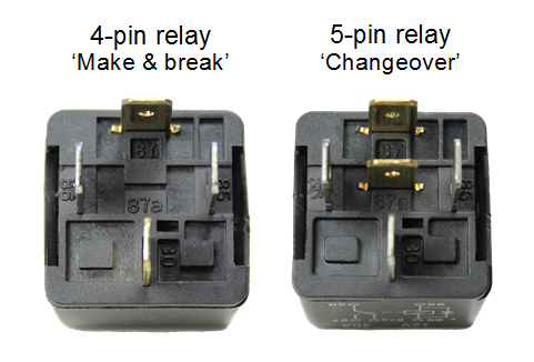
4 Pin Relay Vs 5 Pin Relay 4 Pin Relay And 5 Pin Relay Wiring Diagram 5 Pin Relay Wiring Youtube
Automotive Relay Guide 12 Volt Planet
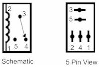
Determine that the relay is an iso micro type.
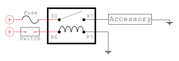
Mini relay 4 pin micro relay wiring diagram.

Bosch 4 Pin Relay Wiring Diagram For Doorbell Symbols Car Relay Diagram Electrical Wiring Diagram

4 Pin 12v 20amp Automotive Micro Relay Make And Break Car Van Bike Y1 Ebay

Usb Wire Diagram Schematic Micro Wiring Connector Colors To With Volovets Info In 2020 Electrical Diagram Circuit Diagram Automotive Electrical

Diagram By Akita Your Diagram Source From Akita Automotive Electrical Relay Automotive Mechanic
Source : pinterest.com
